How to Measure Your Thru Axle Diameter in 3 Easy Steps
First, remove the thru-axle, wipe it clean, and inspect it for an M12 marking; keep any spacers in order.
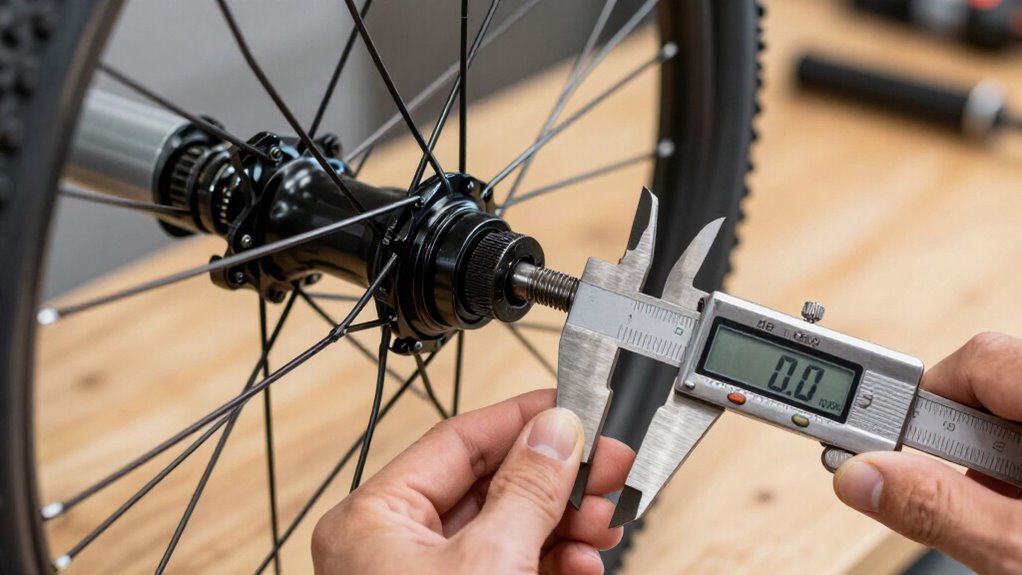
Second, zero digital calipers and measure the smooth shaft, not the threads, head, or shoulder, at three locations, rotating the axle 90 degrees each time.
Third, record the average diameter and thread pitch, then reinstall by hand and torque it to the manufacturer’s specification.
The steps below help you confirm fit and safely avoid ordering an incompatible axle.
Confirm Your Axle Diameter
Remove the thru-axle and check the shaft for laser-etched or printed specifications before measuring; many axles list their diameter, thread pitch, and length.
Compare the marking with the M12 standard used on many disc-brake bikes: the nominal 12 identifies a diameter of about 12 mm. Don’t mistake thread dimensions for the axle standard. On an M12 axle, external threads read 11.85–11.95 mm, while the internal thread area in the frame insert or nut typically reads 12.05–12.15 mm. Confirm diameter alongside pitch, commonly 1.0, 1.5, or 1.75 mm, to prevent ordering an incompatible axle.
If your bike uses R.A.T., Naild, Mavic Speed Release, or Surly’s system, don’t assume a standard size. Follow its specification or your bike manufacturer’s supported-system list; incorrect parts can misalign wheel or damage interfaces.
Use Digital Calipers
Use zeroed digital calipers to measure the clean, smooth shaft section of the thru-axle, not the threads, shoulder, or head. Wipe the measurement area with a lint-free rag and 70% isopropyl alcohol. Check the battery, close the jaws, and press zero on a padded bench.
- Hold the jaws perpendicular to the axle axis, with their faces parallel to it.
- Use light, consistent pressure; don’t squeeze, which can distort readings or damage the tool.
- Measure near the inner, middle, and outer shaft, rotating the axle 90 degrees.
Record readings to 0.01 mm. Calculate the mean and note the maximum variation for taper or ovality. Consumer calipers typically carry ±0.02–0.03 mm uncertainty. Keep the axle and calipers at room temperature, away from sunlight or heat.
Step 1: Remove the Thru Axle
Release the wheel and withdraw the thru-axle from the fork or frame so you can inspect and measure the shaft directly. Support the bike securely before loosening the axle and keep the wheel controlled as it comes free. Check the axle for printed or etched specifications, such as M15x1.0, M15x1.5, or M14x1.5, and record them.
If no marking appears, retain the axle and any spacers in their installed order until you’ve taken the diameter reading. Confirm that the system isn’t proprietary, including R.A.T., Naild, Mavic Speed Release, or Surly; these designs may require a factory replacement. With the axle removed, measure the shaft itself, not hub width or overall frame-specific fit dimensions, which vary between frames and don’t establish diameter. Do not force removal.
Step 2: Clean the Axle Shaft
Wipe the removed thru-axle with a clean, dry rag until the smooth shaft and threaded end are free of dirt, grease, corrosion, and residue. Work over a clean, well-lit surface so debris doesn’t enter the hub, dropout, or frame insert. Inspect the threads closely and remove grime from each thread valley and crest with the rag; packed contamination can obscure their shape and lead to an incorrect reading.
Don’t apply lubricant, anti-seize, solvent film, or protective coating before you finish the inspection, because residue can alter caliper contact. An M12-style axle’s external threads may read 11.85–11.95 mm, while the frame insert is typically 12.05–12.15 mm. Keep these threaded dimensions separate from the shaft’s nominal size. Let the axle dry completely before proceeding to verification.
Step 3: Measure Smooth-Shaft Width
With the axle removed and clean, place caliper jaws on the clearest straight section of the smooth, unthreaded shaft, away from the head, shoulder, threads, tapers, and stepped areas, and read the outside diameter in millimeters. Keep the jaws square to the shaft and apply only light contact pressure; squeezing can skew the tool or mark soft surfaces.
Measure at two or three points along the straight section to check for wear or deformation. Record the smooth-shaft result and identify the nearest M12-family category; a 12×100 or 12×142 system normally uses a nominal 12 mm axle. Don’t substitute a thread measurement: external threads may read about 11.85–11.95 mm, yet they don’t define the shaft width. Diameter alone won’t establish thread pitch or axle length, so retain your value.
Step 4: Read the Caliper Scale
Read the caliper in millimeters at a straight, consistent section of the axle’s external threads, measuring the metal screw diameter rather than the wheel or hub. Close the jaws gently on the thread crests without squeezing, rocking, or angling the tool; excessive force can distort the reading or damage a caliper. Keep the beam square to the axle and read the value in mm.
On an M12 thru-axle, an outside-thread reading of about 11.85, 11.95 mm is typical. Don’t confuse this value with the mating frame insert’s internal thread, which commonly measures about 12.05, 12.15 mm. Record the result as shown, including instrument resolution, such as 11.90 mm to the nearest 0.01 mm. This documented measurement lets you compare thread diameter accurately with replacement-axle listings.
Step 5: Recheck at Three Shaft Points
Next, check the axle at three straight-shaft points: near one seated end, at the center, and near the opposite end. Place clean caliper jaws squarely across the same smooth shaft feature each time, then record every reading separately. Consistent measurements confirm that the shaft hasn’t worn, tapered, or deformed.
Don’t compare a smooth-shaft reading directly with a threaded-section reading. Threads commonly measure slightly below nominal diameter: an M12 axle’s external threads may read 11.85, 11.95 mm, while matching internal frame threads may measure 12.05, 12.15 mm. If your readings differ noticeably, clean the axle, reposition the jaws, and verify that you haven’t measured a thread crest instead of the shaft. For replacement matching, use the diameter that corresponds to the threaded standard, such as 12 mm/M12, and confirm its pitch separately.
Step 6: Reinstall Axle to Manufacturer Torque
Before applying torque, thread the axle into the frame or fork by hand to confirm that it engages smoothly and that the pitch is correct; common M12 pitches include 1.0, 1.5, and 1.75 mm. Stop if you feel binding or resistance; inspect the threads before continuing. Confirm that the axle interface seats squarely on the required surface, whether flat, conical, or recessed.
Use a calibrated torque wrench and apply the frame, fork, or axle manufacturer’s specified torque to the threaded end. Classified, for example, specifies 4 Nm. If your system has a smart thru-axle/lever unit, tighten it as instructed; Classified specifies 10 Nm. Finally, verify that the wheel is seated and centered in the dropouts. Incorrect seating can alter brake alignment despite correct torque.
Match Measurement to Hub Specification
Use the hub designation as your primary reference. For a 12×142 hub, choose an M12/12 mm axle and confirm its measurement. An M12 axle’s external threaded diameter commonly reads 11.85–11.95 mm; this slight undersize is normal for metric threads.
If markings are absent, start with the hub’s 12 mm specification and compare your thread measurement with that expected range. Don’t size an axle from 142 mm: it only describes dropout spacing. After confirming diameter, verify pitch, thread length, and axle length against frame/fork specifications. Wrong diameter damages interfaces and misaligns wheel.
Oversized Reading? Avoid Thread Peaks
If your caliper shows a slightly oversized result, center its jaws across the threaded shaft rather than catching a burr or unusually high thread crest. Close the jaws lightly, keep them square to the axle, and repeat the check at several positions. A nominal M12 external thread often reads 11.85, 11.95 mm; its mating internal thread may measure 12.05, 12.15 mm. That clearance is normal.
| Check | What you should do |
|---|---|
| High crest | Reposition jaws centrally |
| Burr or coating | Ignore variation; recheck |
| Pitch choice | Match 1.0, 1.5, or 1.75 mm exactly |
Don’t use a peak-to-peak result to identify thread family. Crest wear, coating, or taper can inflate a reading and suggest the wrong pitch.
Diameter is only a sanity check; exact pitch determines safe engagement and compatibility during installation.
Record Diameter in Bike Log
For a dependable replacement record, remove the thru axle and log its diameter marking, often “M12,” from the shaft, lever, or head area. Photograph the marking and enter it in your bike log exactly as shown. If no diameter appears, use calipers to measure the outside thread diameter and record the reading in millimeters; an M12 thread commonly measures about 11.85–11.95 mm.
Also log thread pitch, such as 1.0, 1.5, or 1.75 mm, because matching diameter alone doesn’t ensure safe engagement. Identify the dropout seat as flat or conical, since the axle head must match its contact geometry. Finally, record shaft length excluding the head and any tapered spacer. Keep this measurement within the replacement’s ±2 mm tolerance to prevent poor clamping, wheel misalignment, or damage.
Conclusion
To confirm your thru-axle diameter, remove the axle, clean its smooth shaft, and measure it with digital calipers away from the threads. Compare your result with the hub and frame specifications, not thread-peak readings. Reinstall the axle using the manufacturer’s stated torque, and check that it seats fully and securely.
Record the diameter and axle standard in your bike log. Accurate measurement helps you select compatible parts and avoid unsafe fitment or damage during riding.