Bike Thru-Axle Size Chart: 12mm, 15mm & 148×12 Explained
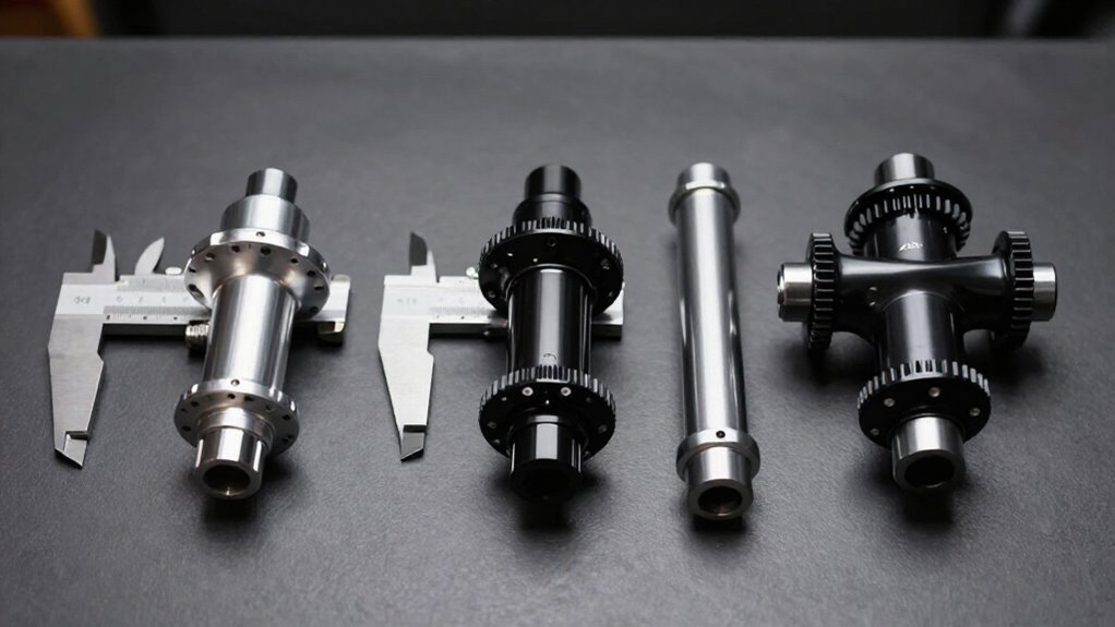
Identify a bike thru-axle by measuring dropout inside-face spacing (OLD), shaft diameter, overall axle length, thread pitch, and thread engagement.
A 12×142 or 12×148 label means 12 mm diameter and 142 or 148 mm OLD; Boost rear is 148 mm, not interchangeable with 142 without approved parts.
Front 15 mm axles are common on MTB forks, while 12 mm suits many road hubs.
Confirm pitch, insert depth, and trainer-specific adapters before installation.
Further guidance follows.
Measure Dropout Spacing Before Ordering
Measure dropout spacing first: the over-locknut dimension (OLD) is the distance between the inside faces of the fork or frame dropouts. Use calipers with the wheel removed, measuring dropout-to-dropout clearance rather than the axle itself. Record this value in millimetres before selecting a hub or replacement axle.
Typical references include 100 mm at the front, 142 mm at the rear, and 148 mm for a Boost rear. OLD defines the hub’s required seating width; it doesn’t by itself define a compatible axle.
Next, confirm shaft diameter: 12 mm suits most road and Boost hubs, while 15 mm remains common on many MTB forks; certain downhill forks use 20 mm. Measure total axle and through lengths, too. Hidden or Stealth inserts may require additional axle length.
Common Thru-Axle Thread Pitches
Thread pitch determines whether a thru-axle will engage the frame or fork safely, even when its diameter and length appear correct. You must match the axle’s metric thread to the dropout insert; diameter alone doesn’t establish compatibility. Never force engagement: a mismatched pitch can cross-thread or weaken the retaining interface.
| Size | Pitch | Identification |
|---|---|---|
| M12 | 1.0 | Fine; Syntace-style |
| M12 | 1.5 | Medium; commonly encountered |
| M12 | 1.75 | Coarse; many stock axles |
| M15 | 1.0–1.75 | OEM-specific; verify |
Use a thread gauge or OEM specifications before ordering. M12×1.0 is fine; M12×1.5 is medium; M12×1.75 is coarse. M15 varies by fork model: Fox and RockShox designs may use different thread forms or diameters. Confirm pitch, head interface, and thread engagement. If markings conflict, consult current OEM documentation directly for replacement selection.
O.L.D.: Over-Locknut Dimension
Once you’ve matched the thread pitch, confirm the hub’s O.L.D. (over-locknut dimension): the distance between the inside faces of the fork or frame dropouts where the hub end caps seat. This measurement defines the hub spacing your frame or fork accepts. In a label such as 12 × 142, 142 identifies O.L.D.; 12 identifies nominal axle diameter.
Don’t confuse O.L.D. with required overall axle length. The axle must span the dropout structure and engage its threaded insert to the specified depth, so its head-to-thread-end length must precisely match the manufacturer’s published design. Hidden inserts can increase installed hardware depth without changing apparent spacing.
Measure between the inside dropout faces with the wheel removed. Then verify end-cap fit, axle length, and the OEM part number.
Front 100×12 Axle Standards
A front 100×12 standard uses 100 mm over-locknut spacing and a 12 mm axle, a common configuration on road and gravel disc-brake forks.
You must match the hub end caps to the fork’s closed dropouts, then confirm axle length, thread pitch, and head interface, not just the 100×12 label.
Correct fit centers the wheel and maintains intended disc-rotor alignment in the caliper.
What 100×12 Means
Confirm that shaft measures 12 mm, then check the manufacturer’s specified overall length, measured excluding the head. Also match thread pitch, commonly about 1.5 mm but not universal, and the threaded engagement length.
Finally, match the head-seat geometry: a conical X-12 cone axle won’t seat in a fork designed for a flat head.
Road And Gravel Applications
For disc-brake road and gravel bikes, 12×100 mm is the prevailing front thru-axle standard: a 12 mm shaft passing through fork dropouts spaced 100 mm apart. When you’re identifying a front road or gravel axle, treat 12×100 as two separate nominal dimensions: 12 mm indicates shaft diameter, and 100 mm indicates the inside distance between dropout faces. It doesn’t specify the axle’s overall length.
On many disc-road forks, the required axle measures approximately 118 mm or more when measured without its head, because the threaded section extends beyond the 100 mm span to reach the fork’s threaded dropout. Accordingly, don’t order a replacement from the 12×100 label alone. You’ll also always confirm total axle length and thread pitch to ensure full, secure engagement.
Hub And Fork Compatibility
Most road disc hubs and forks use the 100×12 front standard: 100 mm dropout spacing and a 12 mm thru-axle bore. Your hub’s end caps must position the hub 100 mm between the fork dropouts and accept a 12 mm axle.
A 12×100 hub fits only a fork with matching 12 mm bore and 100 mm spacing. It won’t directly fit a 15×100 fork because the larger fork bore and hub end-cap system differ. Likewise, it isn’t interchangeable with 15×110 Boost, whose wider spacing changes hub and fork geometry.
Confirm the fork’s stated axle diameter and dropout spacing, then verify the hub manufacturer’s end-cap configuration. Don’t infer compatibility from a generic thru-axle label. Correct matching centers the wheel, seats both end caps fully, and preserves disc-rotor alignment in the caliper. This standard applies to the hub’s over-locknut dimension, not merely the fork’s external width.
Axle Length And Thread
A 100×12 front label doesn’t specify a complete replacement axle: 100 mm denotes the fork’s inner dropout spacing, while 12 mm denotes axle diameter. You must match total axle length, measured excluding its head, to your fork’s dropout design. A road 12×100 axle often measures about 118 mm or longer because it crosses fork legs and engages the threaded dropout.
Confirm threaded-section length and pitch before ordering. Front axles use pitches such as 1.0, 1.5, or 1.75 mm; many forks use 1.5 mm. A mismatched pitch won’t tighten and can damage fork threads. Also identify head interface: it may seat on a flat face or a conical X-12-style recess. Record diameter, total length, thread length, pitch, and head type, then match OEM specification.
Rotor Alignment Considerations
Correct axle length and thread pitch also preserve rotor alignment on a front disc-road 100×12 setup. Here, 100 mm specifies the fork’s inner dropout-face spacing, while 12 mm specifies axle diameter; neither dimension defines total axle length. You must use an axle whose shoulder-to-threaded-end length, pitch, and engagement match the fork specification. A mismatched axle can bottom out, provide inadequate thread engagement, or prevent the hub from seating squarely in the dropouts.
When the hub seats correctly, the thru-axle clamps and locates the wheel consistently, keeping the disc rotor centered in the caliper more reliably than a quick-release system.
After installation, tighten the axle to manufacturer torque, spin the wheel, and check for rotor rub. If rubbing persists, verify axle seating and compatibility before caliper adjustment.
Distinguish 142×12 From Boost
Although both use a 12 mm rear axle, 12×142 and Boost 12×148 specify different hub/dropout spacings: 142 mm versus 148 mm. You identify 142×12 as a 12 mm axle system with 142 mm rear over-locknut dimension between the dropout inner faces. It is common on road-disc frames and preserves hub, chainline, and rotor relationships associated with 135 mm QR layouts.
Boost uses 148 mm rear spacing and moves the hub interfaces 6 mm farther apart. This width increases spoke bracing angle and can improve wheel rigidity. Check your frame and hub specifications: road frames typically state 12×142, while Boost-compatible MTB, gravel, and e-bike frames state 12×148 rear. Don’t install a 142 wheel/axle assembly in a 148 frame, or vice versa, unless approved alternate parts.
Verify Thread Engagement Depth
Thread engagement is as critical as axle diameter and hub spacing: the axle’s thread pitch must match the frame or fork insert exactly, commonly 1.0, 1.5, or 1.75 mm. A mismatched pitch may seem to start, but it’ll grab poorly or cross-thread the insert.
You must also verify that the threaded section reaches sufficient insert depth to clamp the axle end-cap firmly against both dropout faces at specified torque. Neither 12 mm nor 15 mm diameter, and neither 142 nor 148 mm OLD, establishes threaded length. If the axle bottoms out before clamping, or only its final threads engage, don’t ride it.
Compare it with a known-correct axle, or measure insert depth, then match total axle length and thread length to the manufacturer’s specification exactly.
Direct-Drive Trainers Require Axle Adapters
Direct-drive trainers don’t normally use your bike’s stock rear thru-axle: they clamp the rear dropouts through a trainer-specific axle adapter with the necessary stepped or keyed interface. Although your wheel normally mounts when its axle threads into the dropout, the trainer’s clamping mechanism needs its own interface geometry. Choose an adapter specified for your trainer and rear standard, such as 12×142 mm or 12×148 mm Boost. Don’t presume equal dropout spacing guarantees interchangeability. The adapter must match axle diameter and the trainer’s keyed or stepped contact features; 12 mm and 15 mm hardware aren’t exchangeable. Check the trainer manual and use its listed adapter-kit part number. Confirm manufacturer compatibility for thread pitch and axle length, which can differ among frames where OLD dimension matches.
Inspect Derailleur Hanger Alignment
Before adjusting cable tension or limit screws, inspect the derailleur hanger for alignment and secure seating. A bent or partially seated hanger prevents indexing regardless of adjustments. Don’t diagnose drivetrain faults until you verify its position.
- Visually check that the hanger sits in the rear-wheel plane without twist or clocking.
- Remove the wheel and confirm the hanger mounts flush against the frame.
- Check fastening hardware is fully tightened to the manufacturer’s specified torque.
- Use a straightedge to identify obvious deviation from the intended plane.
- Use a hanger-alignment gauge to measure angle at several cassette positions; rotation can reveal changing gaps.
Perform inspection after crashes or wheel/frame contact. If misaligned, realign or replace the hanger before precisely setting high- and low-limit positions or cable tension.
Measure Axle Overall Length
Measure the thru-axle’s overall length from the end of its shaft or threaded portion to the opposite end, excluding the head that bears against the dropout. Use a caliper or steel rule and record the dimension in millimeters. This measurement covers the shaft and threaded section, not a separate head or seat. Diameter alone, 12 mm or 15 mm, doesn’t establish replacement compatibility.
- Remove the axle before measuring.
- Start at the shaft’s outer end.
- Stop at the opposite threaded end.
- Exclude every head, lever, and bearing seat.
- Compare length with listed diameter and thread pitch.
Different brands pair identical diameters with different overall or threaded lengths.
Confirm the candidate axle reaches the threaded dropout, clamps firmly, and doesn’t bottom out; it must provide adequate thread engagement.
Conclusion
Before you order a replacement thru-axle, confirm your frame’s dropout spacing, hub O.L.D., axle diameter, thread pitch, and overall length. Don’t confuse 142×12 with 148×12 Boost: their spacing and chainline requirements differ. Measure thread engagement and inspect the derailleur hanger for alignment or damage.
For front hubs, verify whether you need 100×12 or 15 mm. If you use a direct-drive trainer, install its specified adapter; don’t force your road axle into a trainer system unnecessarily.