
Bike Maintenance Tools Glossary: Know Every Tool by Name
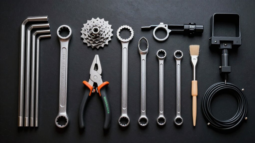
Match hex keys (2–8 mm) and Torx bits, commonly T25/T30, fully to each fastener before turning. Use a Presta core wrench only on removable cores.
A rotor truing fork corrects small lateral bends.
For cassettes, a chain whip prevents freehub rotation while a matched lockring tool turns the lockring.
Remember the left pedal loosens clockwise.
Follow carbon-steerer torque limits, and use a shock pump for suspension pressure.
The sections ahead explain safe use and care.
Identify Hex and Torx Sizes
Identify the bolt head before applying force, because a mismatched tool can round the fastener or damage the component. Hex (Allen) bolts use metric sizes. Keep a starter set containing 2, 2.5, 3, 4, 5, 6, and 8-mm keys so you can fully engage common fittings. Insert the key straight, then confirm it seats to the bottom before turning.
Use an L-handle wrench for 6–8-mm bolts when leverage is necessary, but don’t exceed the component’s specified tightening torque.
Torx fasteners have star-shaped recesses and require matched Torx wrenches, not torque tools. Check the size marking; T25 and T30 occur often on bicycles. A three-way Torx tool with T25, T27, and T30 supports quick service. Apply pressure squarely and stop if engagement feels incomplete immediately.
Presta Valve Core Wrench
A Presta valve core wrench is a small tool that fits the flats on a removable Presta valve core, letting you loosen, remove, or snug the core without damaging the thin stem. Use it only on removable cores: open the tiny top nut, seat the socket over the flats, then turn counterclockwise to remove or clockwise to install.
| Situation | Action | Feeling |
|---|---|---|
| Slow core leak | Snug gently | Reassured |
| Sealant refill | Remove core | Prepared |
| Damaged core | Replace it | Confident |
Don’t use pliers or force. The fine threads strip easily, and a bent core can leak suddenly.
Tighten finger-snug, then add only a slight wrench turn. Check for hissing after inflation, reinstall the cap, and carry a corrosion-resistant steel tool plus spare cores for tubeless service today.
Rotor Truing Fork Terminology
A rotor truing fork, also called a rotor straightener or disc brake rotor adjustment tool, corrects lateral bends in a disc rotor. You’ll find slotted fork designs in different widths; select a slot that fits the rotor securely, then place it only on the braking track away from cutouts and edges.
Identify rotor rub by spinning the wheel and listening for pad contact, then make small corrections and verify clear, consistent rotation before riding.
Rotor Truing Fork Definition
Precision defines a rotor truing fork: it’s a hand tool that aligns over a disc brake rotor so you can apply controlled pressure to small bends. You use it to correct localized warps that create intermittent caliper rub, often after heat exposure, an impact, or a pad or rotor alignment change.
Common Fork Designs
Common rotor truing fork designs use a rigid slotted body to capture the brake disc and apply small, controlled bends at a high spot. Basic hand forks are flat steel levers with one or more slots; you place the opening over the rotor and gently correct its plane.
Other designs pair the fixed fork body with an adjustable alignment tip. As you rotate the wheel, the tip identifies lateral wobble near the caliper, letting you make incremental nicks of correction rather than one large bend.
Keep the tool clear of pads, pistons, and spokes. Work on a cool, clean rotor, use light force, and spin-check after every adjustment. Replace a cracked, deeply scored, or persistently warped rotor. Don’t attempt to straighten a rotor with damaged mounting hardware or questionable brake performance.
Slot Width Selection
For rotor truing forks, slot width is the guide-gap dimension that engages the rotor track, not the rotor’s diameter or the fork’s overall size. Select a width that matches your rotor’s thickness and mounting and caliper-hardware geometry. Check manufacturer specifications before buying: reputable listings identify supported rotor thicknesses, standards, axle types, or an exact fork model.
A slot that’s too narrow can bind or fail to seat, which can damage the tool or encourage unsafe force. A slot that’s too wide allows slop, reducing control and straightening accuracy. Don’t assume forks with similar handles or overall dimensions share the same guide gap.
Compare the fork’s stated interface range with your rotor type and hardware arrangement. If unsure, use manufacturer guidance; brakes are safety-critical.
Correct Rotor Placement
Correct rotor placement keeps each truing correction tied to the actual lateral wobble rather than a changing reference point. Set the rotor truing fork’s fixed pointer just off the rotor, then rotate the wheel by hand. Keep the pointer aligned at one consistent radius from the hub, typically near the rotor’s outer edge, and reference the same thickness location on every rotation.
This setup lets you isolate the exact section that deviates from the rotor’s plane without chasing false movement caused by shifting tool position. Insert the affected section into the appropriate fork slot and apply light, controlled pressure. Make only small corrections, checking the same reference point after each pass. Don’t lever aggressively or alter pointer position mid-process; inconsistent placement produces inaccurate bends and can leave the braking surface improperly aligned.
Identifying Rotor Rub
With the reference point set, identify rotor rub by spinning the wheel and watching the rotor pass through the caliper. Listen for scraping, grinding, or squealing and compare clearance on each side of the rotor. An uneven gap that changes at one point indicates lateral runout, a wobble spot. Constant contact may require checking caliper alignment, wheel seating, and axle security before you identify the rotor as the cause.
A rotor truing fork is a hand tool associated with correcting. Its slotted end engages a section of rotor while its handle provides leverage. If the wheel is removed, a rotor that appears crooked relative to the brake pads indicates rotor alignment, not pad contamination. Don’t touch a hot rotor; inspect for cracks or damage.
Safe Straightening Technique
A rotor truing fork lets you make small, controlled bends that bring a warped disc rotor back into alignment and stop pad rub. Rotate the wheel slowly and watch the gap between rotor and pads to locate the high spot. Position the fork over that section, aligning its slot with the direction of the wobble. Apply light, steady pressure at one point, nudging the high spot toward the low spot.
Release the fork, spin the wheel, and check clearance again. Work in tiny increments rather than trying to correct the entire bend at once. Keep each adjustment deliberate and consistent. If rubbing remains after careful truing, inspect the rotor condition; severely heat-warped or cracked rotors require replacement, not further straightening before riding the bike safely.
Avoiding Rotor Damage
Prevent rotor damage by understanding how a rotor truing fork applies force before you make any correction. The adjustable tip, sometimes called the knuckle, contacts the rotor edge, while the pivot and handle give you leverage. Locate the rubbing spot by spinning the wheel and watching the rotor pass through the caliper.
Then position the tip at the affected area and apply a tiny bend opposite the wobble.
Don’t twist, pry aggressively, or attempt to straighten the rotor in one pass. Recheck clearance after every adjustment; several small corrections protect the thin track better than one large correction. Work with a clean, safe brake system. A crescent wrench can move rotor, but its imprecise contact makes damage more likely than with a purpose-made fork.
Cleaning And Storage
After each use, wipe brake dust and moisture from the rotor truing fork with a clean, dry cloth before returning it to your tool kit. Clean, dry surfaces prevent the tool from transferring abrasive grit to rotor, pads, or wheel, and limit fork corrosion.
Inspect hook or adjustment tips before storage. Clear embedded debris, then place fork in a dedicated pouch or divided tray, away from tools that can dull or bend its edges. Keep it away from lubricant and loose metal.
If your truing fork includes a gauge, scale, or adjustable clearance point, leave it in its specified storage position. Don’t force the mechanism closed or locked: distortion reduces accuracy when you later apply controlled pressure to correct rotor wobble during truing work.
Chain Whip vs Lockring
A chain whip holds the cassette stationary, while a lockring tool engages the lockring so you can loosen or tighten it without damaging its splines. You need both tools for most cassette removal because the freehub otherwise spins under applied torque.
Confirm that the lockring tool matches your cassette system, secure the wheel, and apply controlled force.
Different Roles
Although they’re commonly used together, a cassette lockring tool and chain whip perform different jobs: the lockring tool engages and turns the cassette’s lockring, while the chain whip grips a sprocket to stop the cassette and freehub from rotating.
You need both tools for safe service. The lockring tool applies loosening or tightening torque to the lockring; the whip provides counterhold. Without the whip, the freehub may turn, leaving the lockring unchanged and encouraging hand force. Select a lockring tool that matches your cassette’s lockring interface, including the Shimano/SRAM-style spline pattern. During reinstallation, tighten the lockring to the manufacturer’s specified torque. A secured lockring helps prevent cassette movement, shifting problems, and drivetrain noise. Keep your hands clear of teeth and stabilize the wheel before applying force.
How Each Tool Works
Understanding the separate actions makes cassette service safer: the chain whip engages a cassette cog and holds the cassette/freehub against rotation, while the correctly matched lockring tool seats in the lockring splines or notches so you can turn it with a wrench or ratchet.
Position the whip’s chain section securely on an appropriate cog and keep your hand clear of sharp teeth. Its handle provides leverage while the engaged cog resists freehub rotation. Inspect the chain section for wear; a slipping whip can cause sudden hand movement.
For the lockring tool, confirm its spline or notch pattern matches the cassette standard before applying force. Seat it fully and squarely to avoid damaging the interface. During installation, maintain alignment and use the specified torque value when available for your cassette.
When Both Are Needed
When you remove or install a cassette, use both tools: the chain whip counterholds the cassette and freehub, while the correctly matched lockring tool engages and turns the lockring that secures the cassette to the hub. During removal, position the whip on a cassette sprocket so it resists rotation, then turn the lockring tool with controlled force. The whip supplies the opposing force; the lockring tool alone cannot keep the freehub from turning.
During installation, use the same counterhold as you tighten the lockring. Keep your hands clear of chain teeth, stabilize the wheel or bike, and maintain firm tool engagement before applying load. Don’t substitute improvised grips or rely on the drivetrain to resist torque. Using both tools prevents slips, reduces injury risk.
Compatibility And Proper Use
Use a lockring tool that matches your cassette’s lockring interface—commonly Shimano/SRAM-type splines—and seat it fully before turning it with a ratchet, socket, or adjustable wrench. For removal, wrap the chain whip’s chain securely around a sprocket so it resists cassette rotation. Hold the whip against the lockring tool’s loosening force; opposing forces let you break the lockring free without slipping or rounding its splines.
During installation, use the whip only to stabilize the cassette while you tighten the lockring. Follow the cassette manufacturer’s torque specification, often about 35–40 Nm for modern cassettes, rather than relying on feel. Remove the lockring, then lift the sprockets off by hand; the whip doesn’t pull the cassette or freehub body. Wear gloves and keep fingers clear of sprockets.
Removing Left-Hand Pedal Threads
Although most bicycle fasteners loosen counterclockwise, the left (non-drive-side) pedal uses reverse threads and loosens clockwise when viewed from the left crank arm. Secure the bicycle in a workstand, or brace it firmly on the ground. Fit a 15 mm pedal wrench fully onto the flats; use the pedal’s specified internal hex key if it has no flats.
Pull with controlled force, keeping your knuckles clear of the chainring and frame. Don’t jerk the wrench. If corrosion has seized the threads, apply penetrating fluid as appropriate and increase leverage gradually. Once removed, inspect the crank-arm threads for damage and contamination.
Before refitting, apply waterproof grease to the pedal threads. Start them by hand to prevent cross-threading, then tighten to the pedal manufacturer’s specified torque value.
Carbon Steerer Torque Limits
Carbon steerers demand exact clamping torque because excess force can crush the tube or cause progressive damage that isn’t immediately visible. Use the fork and stem manufacturer’s specified values, not a generic “tight enough” setting. Upper clamp or top-cap areas often require 4–6 Nm, while small pinch bolts may specify about 6–8 Nm.
Verify each fastener’s function: top-cap preload and steerer-clamp bolts don’t share one default torque.
Use a calibrated torque wrench, ideally suited to low ranges, and tighten evenly in stages. Install only approved spacers and clamp parts; stack height and clamp position must match the fork’s design. Inspect near the stem for glossy crush marks, deep indentations, or cracks. If you find any, stop riding and have the fork professionally inspected or replaced.
Shock Pump for Suspension
Suspension setup requires the same measured approach as carbon-component clamping. A shock pump is a high-pressure hand pump that sets your rear-shock air-spring pressure, often near 200–300 psi. Its precise gauge and direct chuck let you reproduce settings safely; a tire pump’s gauge doesn’t provide adequate accuracy.
- Check that the pump head matches your shock’s Schrader or proprietary valve.
- Add or release air in small increments within the manufacturer’s specified psi range.
- Disconnect carefully, then measure sag and adjust toward the bike’s recommended 25–35% target.
Never exceed the shock’s maximum pressure. Consult the suspension manual before changing air-spring tune, and keep hands clear of moving linkage during sag checks. Wear eye protection, inspect the valve cap and seal, and record your final pressure.
Conclusion
Knowing the correct name and purpose of each tool helps you service your bike without damaging expensive components. You’ll identify hex and Torx fittings, use a Presta core wrench correctly, true rotors safely, and distinguish a chain whip from a lockring tool.
Remember that left pedals loosen clockwise, carbon steerers require specified torque, and suspension needs a shock pump. Check manufacturer specifications, use calibrated tools, and stop if threads, fasteners, or components resist firmly unexpectedly.